
#TODO Update README.md
Handles the MultiWii Serial Protocol to send/receive data from boards.
This is a text based / console, no GUI, it works reading data from the multicopter and/or sending commands from a computer via a serial modem. I use this module for doing different request to my multicopters in order to control them wirelessly via a raspberry pie.
Just create a MultiWii object that receives the serial port parameter and then you can ask for a command by using the function getData, a explicit example is on main.py:
serialPort = "/dev/tty.usbserial-A101CCVF"
board1 = MultiWii(serialPort)
    while True:
		print board1.getData(MultiWii.ATTITUDE)
With the example above, you will see a stream of data on your terminal.
If you're using something similar to a naze32 using either baseflight or cleanflight you will be able to ask for attitude and some other commands, but by default you will not be able to use the MSP_SET_RAW_RC to write pilot commands to the multiwii. In order to do that you need to activate (via the baseflight/cleanflight GUI) the SerialRX with the specific type for MSP (MultiWii Serial Protocol). The instructions for doing that on baseflight are:
- Open the CLI (while on the baseflight configurator) and type:
feature SERIALRX
and then type the following lines:
set serialrx_type=4
This will activate "msp" in order to control the multiwii via that protocol. Important: when type=4 is active, standard radio will not work... (at least on the releases I'm using).
Then you can carefully test my example "test-arm-disarm.py"... You will see the motors spin for 3 seconds. ¡¡BE CAREFUL!!
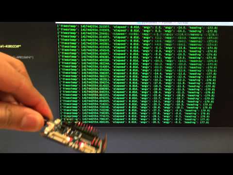
This code has no time.sleep(), so, its very fast and efficient. The output looks like this when asking or ATTITUDE:
{'timestamp': 1417432436.878697, 'elapsed': 0.016, 'angx': -26.8, 'angy': -24.8, 'heading': -84.0}
{'timestamp': 1417432436.894663, 'elapsed': 0.016, 'angx': -26.8, 'angy': -24.7, 'heading': -84.0}
{'timestamp': 1417432436.910673, 'elapsed': 0.016, 'angx': -26.7, 'angy': -24.8, 'heading': -84.0}
{'timestamp': 1417432436.926812, 'elapsed': 0.016, 'angx': -26.7, 'angy': -24.7, 'heading': -84.0}
{'timestamp': 1417432436.942629, 'elapsed': 0.016, 'angx': -26.7, 'angy': -24.7, 'heading': -84.0}
{'timestamp': 1417432436.958657, 'elapsed': 0.016, 'angx': -26.7, 'angy': -24.6, 'heading': -84.0}
{'timestamp': 1417432436.974627, 'elapsed': 0.016, 'angx': -26.7, 'angy': -24.6, 'heading': -84.0}
{'timestamp': 1417432436.990591, 'elapsed': 0.016, 'angx': -26.7, 'angy': -24.5, 'heading': -84.0}
{'timestamp': 1417432437.006598, 'elapsed': 0.016, 'angx': -26.7, 'angy': -24.5, 'heading': -84.0}
{'timestamp': 1417432437.022676, 'elapsed': 0.016, 'angx': -26.6, 'angy': -24.5, 'heading': -84.0}
{'timestamp': 1417432437.038604, 'elapsed': 0.016, 'angx': -26.6, 'angy': -24.4, 'heading': -85.0}
{'timestamp': 1417432437.054619, 'elapsed': 0.016, 'angx': -26.7, 'angy': -24.4, 'heading': -85.0}
{'timestamp': 1417432437.070593, 'elapsed': 0.016, 'angx': -26.6, 'angy': -24.3, 'heading': -85.0}
{'timestamp': 1417432437.086576, 'elapsed': 0.016, 'angx': -26.6, 'angy': -24.3, 'heading': -85.0}
{'timestamp': 1417432437.102768, 'elapsed': 0.016, 'angx': -26.7, 'angy': -24.2, 'heading': -85.0}
{'timestamp': 1417432437.118586, 'elapsed': 0.016, 'angx': -26.6, 'angy': -24.2, 'heading': -85.0}
{'timestamp': 1417432437.134683, 'elapsed': 0.016, 'angx': -26.6, 'angy': -24.2, 'heading': -85.0}
{'timestamp': 1417432437.150524, 'elapsed': 0.016, 'angx': -26.6, 'angy': -24.1, 'heading': -85.0}
{'timestamp': 1417432437.166525, 'elapsed': 0.016, 'angx': -26.6, 'angy': -24.1, 'heading': -85.0}
Using different devices and newer boards you can achieve greater rates of communication, using an oDroid U3 and a naze32 I have achieved close to 300hz.
This code is still somewhat under development, if you found a bug or a improvement, please let me know!!
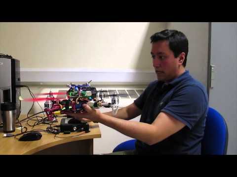
I'm doing systems identification of multicopters being flown by me via a multiwii board. Why do I want to do this? I want to do very precise navigation algorithms using a motion capture system.
Systems identification is a statistical method to build mathematical models of the multicopters, to have excellent control we require a perfect mathematical model. In order to do a good sysid we require data, lots of data, data coming from the board as well as the pilot and the position in the space (motion capture), so, I require raw imu (accelerometers and gyroscopes), pilot commands (rc channels) and position (x,y,z).
So far, I have a position controller working with the multiwii board being flow by simulink using data from the motion capture system and just sending rc channels via a 3DR robotics radio (roll, pitch, yaw, throttle), you can see a video about that here TEGO indoor position control
I works nice... but I want it to work even nicer and better!!! so, we need all the mathematical models and parameters to be as precise as possible, ergo, systems identification required.
I knew that the 3DR radio was not good enough to send data in a fast way to the ground station... So, I put onboard a Raspberry Pie, this computer ask data to the multwii and also to the motion capture system, and saves it... thats it for now.