
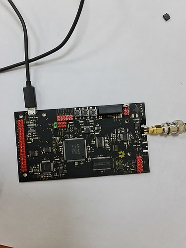
Install jumpers and connectors as indicated in the figure below. Jumpers necessary are the white and the green ones.
pip3 install pyftdi matplotlib numpy scipy
iceprog is the software used to put the fpga on the flash storage on the board, which will be read by the fpga on boot. The easiest way is to :
sudo apt install fpga-icestorm
If this doesn’t work, then this may work:
sudo apt-get install libftdi-dev git gcc
git clone https://github.com/cliffordwolf/icestorm.git
cd iceprog
make
sudo make install
This will create and install the iceprog utility, used to flash the fpga program (bitstream).
Notes for Linux: Create a file /etc/udev/rules.d/53-lattice-ftdi.rules with the following line in it to allow uploading bit-streams as unprivileged user:
ATTRS{idVendor}=="0403", ATTRS{idProduct}=="6014", MODE="0660", GROUP="plugdev", TAG+="uaccess"
This should solve usb access rules.
Download the install pack or by
wget https://github.com/kelu124/un0rick/raw/master/usb/install_pack.zip
Check that the FTDI device is well created by typing:
dmesg
Unzip it, inside, there's the bin to program the fpga :
iceprog usb.bin
There is a test bench for the python lib matching the usb firmware, from the brodie package. Installation is as follows.
mkdir experiment
cd experiment
wget https://raw.githubusercontent.com/kelu124/echomods/master/matty/20201026a/brodie.zip
iceprog un0rick_ms3_icestorm.bin
cd fpga_ctrl/
python3 test.py
which will run a series of acqs and produce a series of images from this acquisition.
In the fpga_ctrl folder, you'll need the csr_map, ftdi_dev.py, and fpga_ctrl files, to import the lib:
from fpga_ctrl import FpgaControl
I encourage the reader to go inside this libs, which are already documented.
then connect to the FPGA
# init FTDI device
fpga = FpgaControl('ftdi://ftdi:2232:/', spi_freq=8E6)
# reload configuration (optional step - just to fill BRAM (DACGAIN registers) with initial values)
fpga.reload()
# reset fpga
fpga.reset()To control the waveform, one would set the fpga.csr.ponw, fpga.csr.interw and fpga.csr.poffw, that are respectively integers for setting the width (timing) of the pulse, width of a relaxation period before damping, and then duration of damping. Unit are (1/128us).
The fpga.csr.initdel register is the delay between the beginning of the acquisiton and the pulse.
fpga.csr.initdel = InitDel
fpga.csr.ponw = PONWidth
fpga.csr.interw = INTERWidth
fpga.csr.poffw = PDAMP
Below is plotted amplitude of an echo as a function of the fpga.csr.ponw for a 4MHz transducer. One sees that a setting at 16 provides most
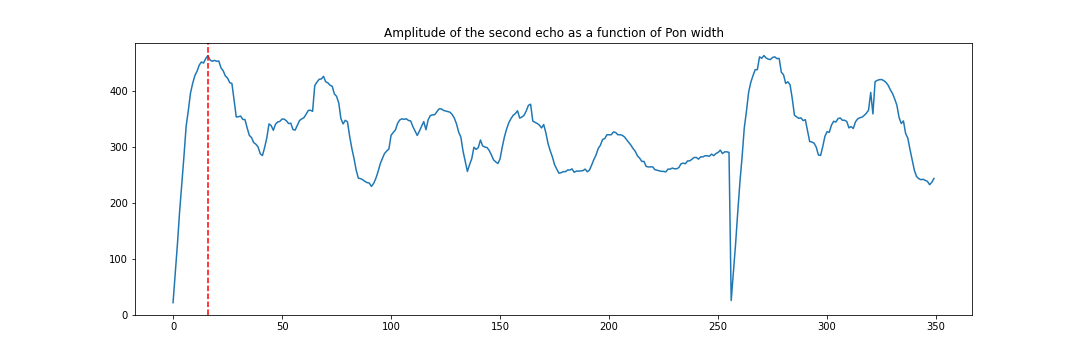
(See full experiment here).
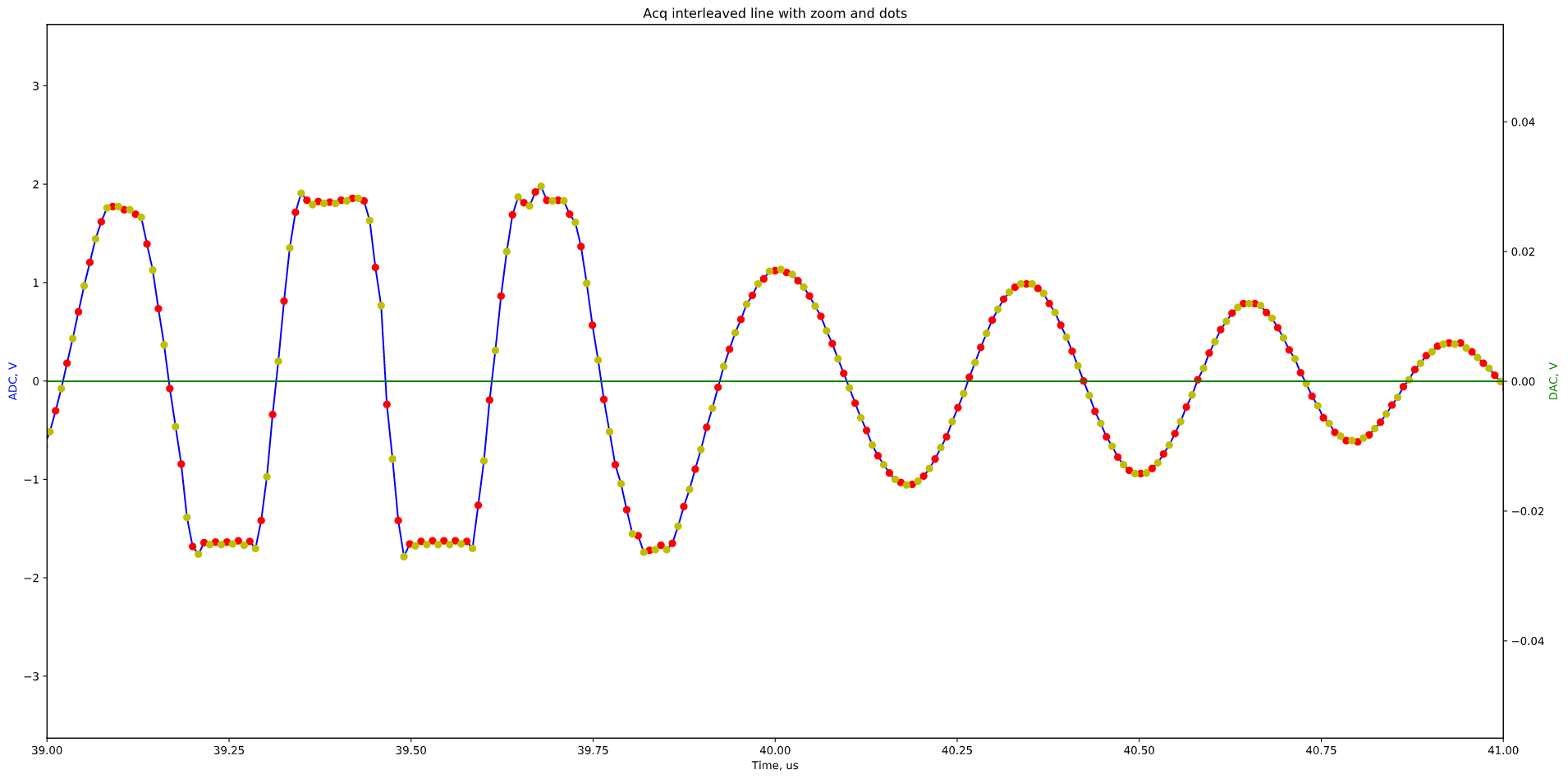
And do acquisitions with acq_res = fpga.do_acquisition(acq_lines=32, gain=gain, double_rate=True) which will return an array of acq_lines acquisitions, of length 256us at 64Msps.
double_rate=True provides a half clock offset to odd lines, so that one can interleave two subsequent acquisition to have, in a fixed setting, a 128Msps acquisition.
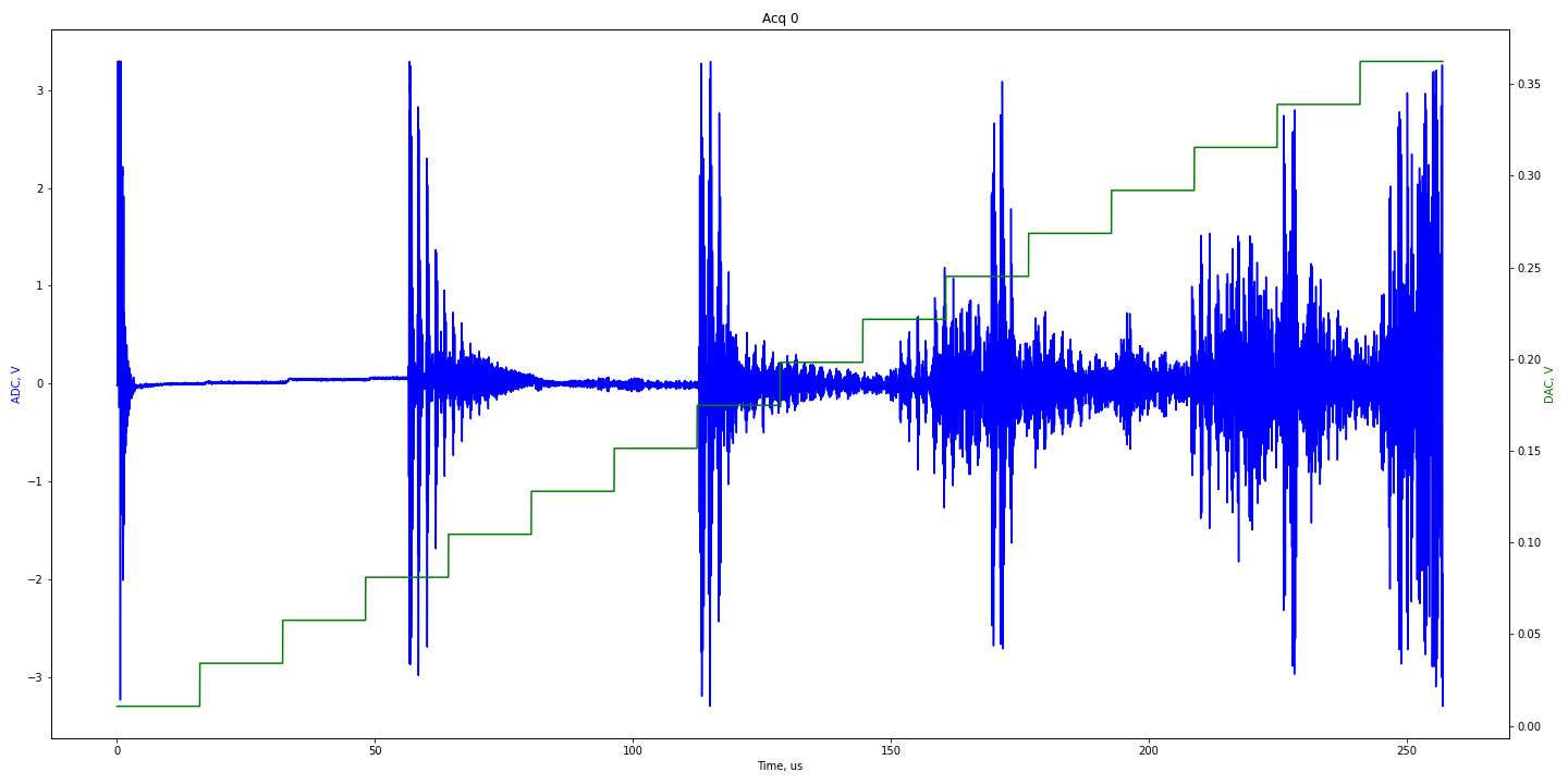
The gain setting is an array of integers, of length 32, that can range from 0 to 1023, controlling gain for each of the 32 8us-segment of acquisition within the 256us line.
fpga.csr.led3 = 0sets LED3 off. led1, led2, led3 are possible, can be set to 0 or 1.fpga.csr.topturnXreads input 1 to 3 on the input header.fpga.csr.jumperXreads jumper 1 to 3 close to the programming jumper.fpga.csr.outXicewrites/reads output 1 to 3.fpga.csr.nblines = acq_lines - 1is the register controlling the number of lines acquired.fpga.csr.dacoutreads the DAC/TGC/VGA level outside of acquisitions.fpga.csr.acqstart = 1to start the acquisitionfpga.csr.drmode = int(double_rate)triggers the interleaving mode.fpga.csr.acqstart = 1to start the acquisitionfpga.csr.acqdoneis equal to 0 during acquisitions.fpga.csr.authorreads the ID of the author of the binary.fpga.csr.versionreads the ID of the author's binary.
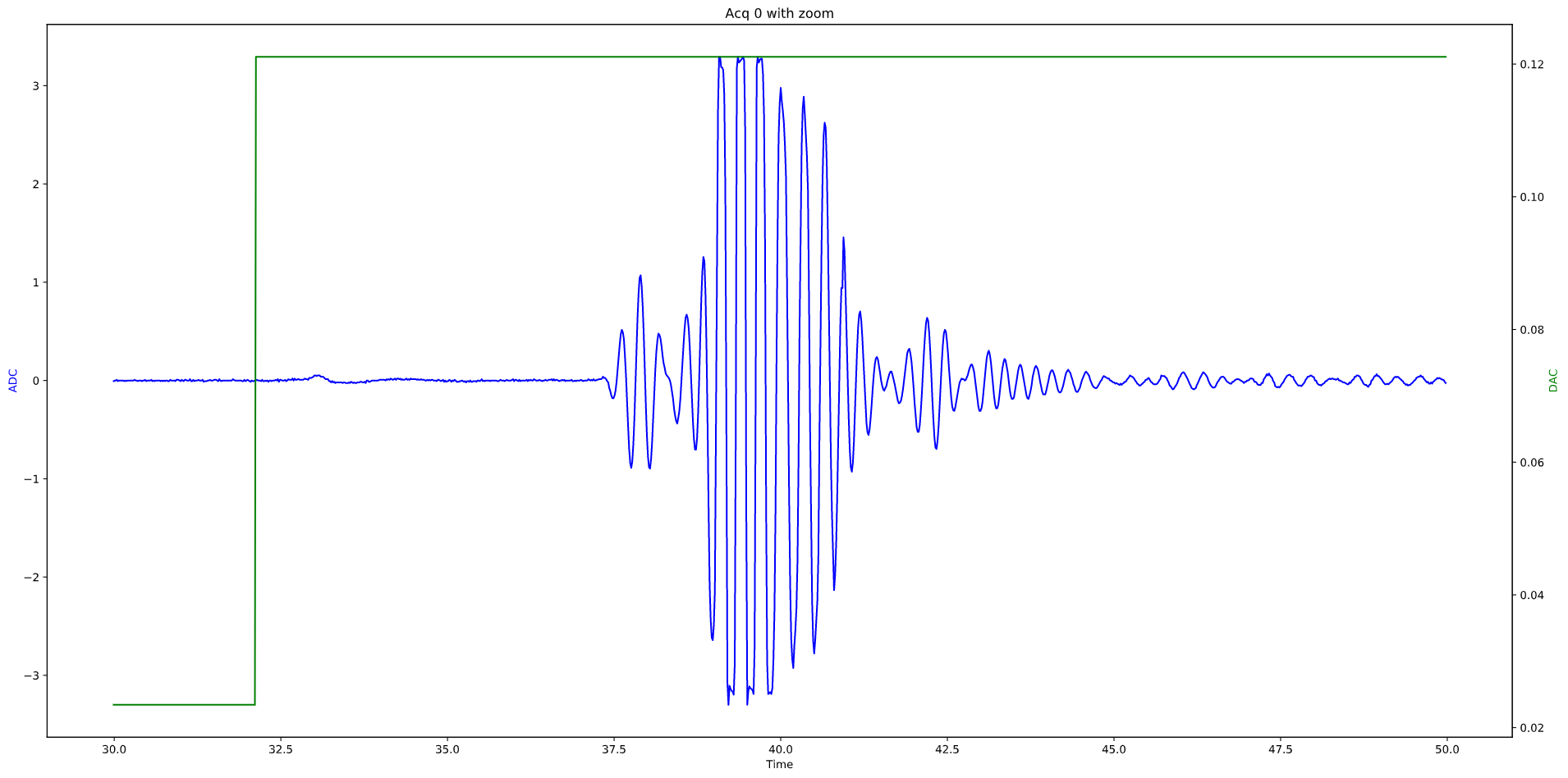
The signal is in blue, the gain levels are in green. Here there are 32 visible steps, of 8us each.
Doublign acquisition speed (yellow and red dots below)
This work is based on two previous TAPR projects, the echOmods project, and the un0rick project - its boards are open hardware and software, developped with open-source elements as much as possible.
Copyright Kelu124 (kelu124@gmail.com) 2020.
- The hardware is licensed under TAPR Open Hardware License (www.tapr.org/OHL)
- The software components are free software: you can redistribute it and/or modify it under the terms of the GNU General Public License as published by the Free Software Foundation, either version 3 of the License, or (at your option) any later version.
- The documentation is licensed under a Creative Commons Attribution-ShareAlike 3.0 Unported License.
This project is distributed WITHOUT ANY EXPRESS OR IMPLIED WARRANTY, INCLUDING OF MERCHANTABILITY, SATISFACTORY QUALITY AND FITNESS FOR A PARTICULAR PURPOSE.