rasdaq is a client and server code for Raspberry Pi to acquire ADC Data from MCP8208 and similar ADC converter chips.
Please download the latest version of Raspberry Pi OS Lite. Newest versions require setting up username / password already in the imager tool. You can also enable SSH from there. Then you can expand file system using the script raspi-config. Then you need a couple of things:
sudo apt udpate
sudo apt -y install git python3-pip
The clone the repository and go inside that directory and type (you may need to provide the command line arg --break-system-packages before the -r and before . below, depending on your system, and how you are using your Raspberry Pi. Please use with care!):
pip install -r requirements.txt
pip3 install .
For uninstalling you can type:
pip3 uninstall rasdaq
The code consists of a separate parts:
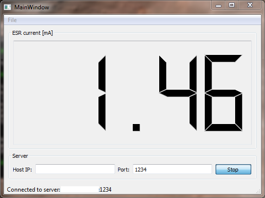
rdcliis the command line interface (CLI) for client and serverrdguiis just a GUI client (viewer) for visual inspection written in QT5 (PyQt5).
You can run the server on the raspberry by:
rdcli --host IP_ADDRESS_OF_RASPBERRY_PI --port 1234 --config rasdaq_config.toml --server
and accordingly the client on any computer by:
rdcli --host IP_ADDRESS_OF_RASPBERRY_PI --port 1234 --config rasdaq_config.toml --client
It is recommended to use numerals for IP address.
To print out the help, type:
rdcli --help
If you do not want to install the code, you can call it as a module:
python3 -m rdcli ...
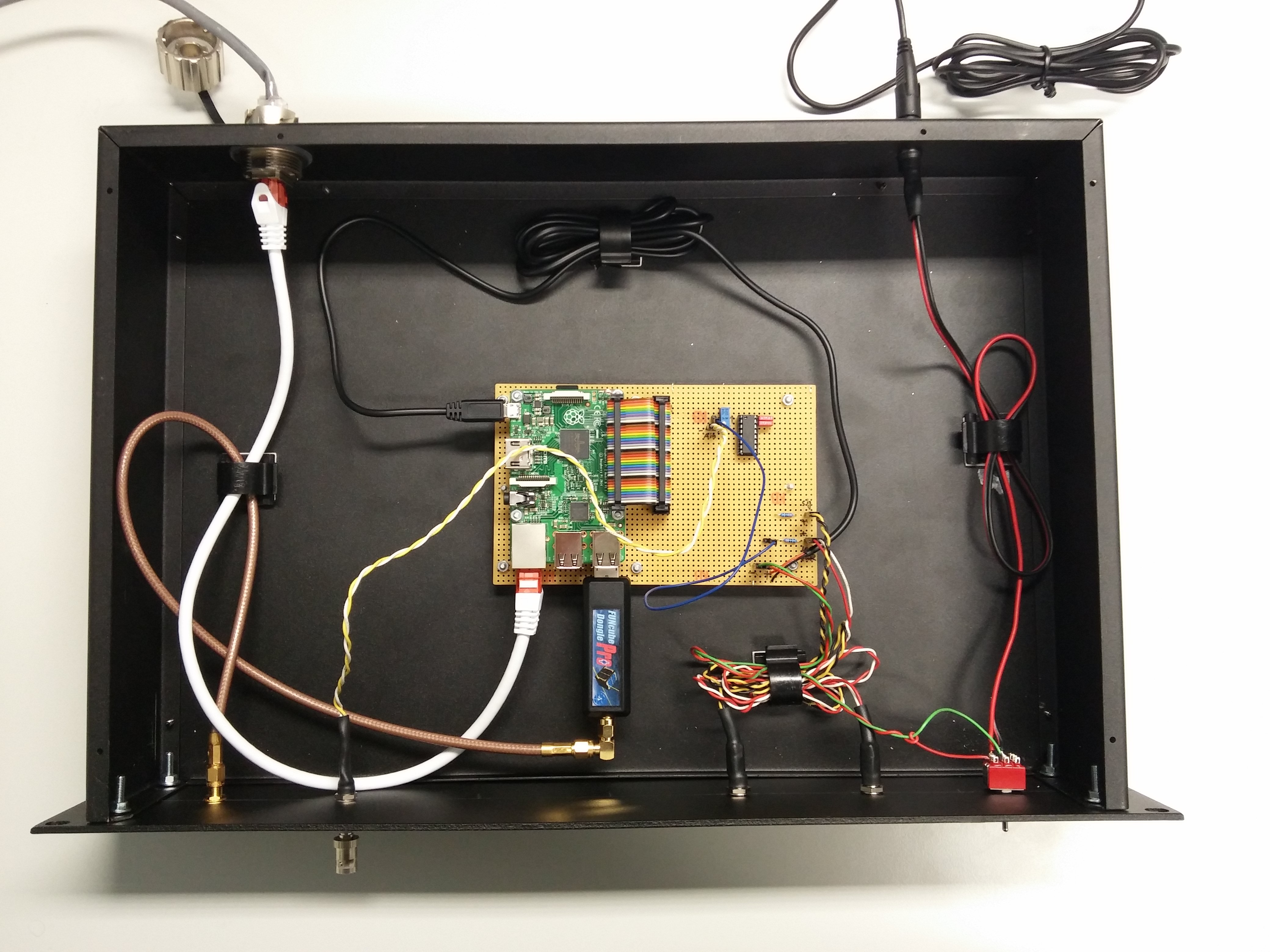
The schematics has been creating using KiCAD. The schematics file is included in the project. A PDF version of the schematics (connection plan) can be found here.
The SPI interface is implemented using own SPI interface based on a python wrapper for spidev. The underlying messaging is accomplished using Zero MQ library in PUB/SUB mode.
First you need to enable SPI function in raspi-config. Here you connect the SPI interface to the MCP3208. Since SPI interface can handle 2 devices, remember if you choose pin 24 as CS, then your device will be known as /dev/spi0.0 and for pin 26 it will be /dev/spi0.1.
| Name | Pin No. |
|---|---|
| LED | 31 |
| RNG0 | 11 |
| RNG1 | 13 |
| RNG2 | 15 |
| MODD | 7 |
| RDDY | 8 |
| PWWR | 10 |
As you can see, an additional LED is connected to the raspberry with a 330 ohm resistor in between.
For accessing different channels on MCP3208 you may choose the following commands. The reason is that you have to keep talking to the device in order to keep the clock running while the chip select signal is low, so that the device can respond accordingly. In the current implementation of the spidev is such that the chip select is taken down per xfer command, and released afterwards. So unfortunately it seems that chip select can not be released from within the xfer command. This means you can not access different channels of MCP3208 at once, but need to send one xfer command for each channel. The explanation is based on the data sheet of the MCP3208, for instance we need to send the following
| 0 0 0 0 | 0 1 1 0 | 0 0 x x | x x x x | x x x x | x x x x |
Navigating from right to left, this corresponds to sending 12 bits in the MSB (B11 - B0). Before the B11, the MSP sends 2 junk bits which we ignore. Before that comes three address bits D2-D0. Before that we send one true bit to signal single ended operation. Before that comes a true start bit. Everything else before that we fill with zeros. All x above can be replaced with 1 or zero. We choose zero. So we have:
| 0 0 0 0 | 0 1 1 0 | 0 0 0 0 | 0 0 0 0 | 0 0 0 0 | 0 0 0 0 |
| 0x0 | 0x6 | 0x0 | 0x0 | 0x0 | 0x0 |
Putting nibbles together into 8 bit bytes we have:
| 0x06 | 0x00 | 0x00 |
so all other channels are similar:
| channel | command |
|---|---|
| 0 | spi.xfer([0x06, 0x00, 0x00]) |
| 1 | spi.xfer([0x06, 0x40, 0x00]) |
| 2 | spi.xfer([0x06, 0x80, 0x00]) |
| 3 | spi.xfer([0x06, 0xC0, 0x00]) |
| 4 | spi.xfer([0x07, 0x00, 0x00]) |
| 5 | spi.xfer([0x07, 0x40, 0x00]) |
| 6 | spi.xfer([0x07, 0x80, 0x00]) |
| 7 | spi.xfer([0x07, 0xC0, 0x00]) |
These values can be sent as binary or decimal of course.
It is interesting to note that smaller devices in the family, such as MCP3201, with one single channel, do not have a DIN pin. So they are purely clock driven. Similar to MSP3208 but only after the address bits, i.e.:
| - - x x | x x x x | x x x x | x x x x |
So basically one can put all zeros in as:
spi.xfer([0x00, 0x00])
but then result might need to be shifted.
Please see the file LICENSE.md for further information about how the content is licensed.
Many thanks goes to HoSnoopy for pointing out a link to the tutorial to GPIO emulation and carlkl for pointing out the wonderful ZeroMQ library.