Northwestern University ME495: Embedded Systems in Robotics (Fall 2015) Instructor: Jarvis Schultz
Team members: Jose Miranda, Sofya Akhmametyeva, Yves Nazon and Tanay Choudhary
- Overview
- [Required tools and set up](#Required tools and set up)
- left_camera_node
- move_arm_node
- [Gazebo world](#Gazebo world)
- [Launch file](#Launch file)
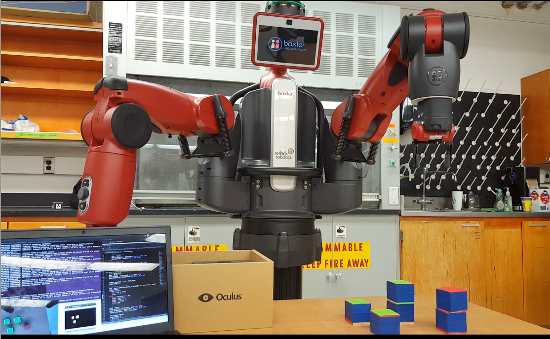
The goal of the project was to have Baxter detect objects via left hand camera and sort them into two boxes based on green and red colors. The MoveIt! package and Baxter's IK Service were leveraged for the movement and path planning. OpenCV was used to perform image processing for object detection.
Please click on the following image to watch the demo!
- Baxter Robot (from Rethink Robotics)
- ROS Indigo for Ubuntu 14.04
- Baxter Setup
- ROS Environment variables must be set properly in order to be able to connect and interface with baxter. It can be useful to add the following lines of code into your .bashrc:
#for baxter simulation
alias bxl="unset ROS_IP; unset ROS_HOSTNAME; unset ROS_MASTER_URI; export ROS_IP=127.0.0.1; export ROS_MASTER_URI=http://localhost:11311"
#for actual baxter
alias bxb="unset ROS_IP; unset ROS_HOSTNAME; unset ROS_MASTER_URI; export ROS_HOSTNAME=<YOUR HOSTNAME>.local; export ROS_MASTER_URI=http://baxter.local:11311"
The left_vision_obj_location.py script instantiates the left_camera_node. This node subscribes to the /cameras/left_hand_camera/image topic and performs image processing, finds the location of a desired object and provides that information via a custom ObjLocation service . For more detail about the various packages and services that were used for the image processing, please see below:
Open CV
We used cv2 package for image processing, as well as CvBridge in order to be able to interface with ROS and Baxter. The left hand camera image was captured, converted to cv2 image and then converted to HSV format as follows:
bridge = CvBridge()
cv_image = bridge.imgmsg_to_cv2(message, "bgr8")
#Converting image to HSV format
hsv = cv2.cvtColor(cv_image, cv2.COLOR_BGR2HSV)
Later the cv_image was thresholded with green and red color HSV ranges in order to pick out the desired objects. Here is a quick example:
thresholded = cv2.inRange(hsv, np.array([low_h, low_s, low_v]), np.array([high_h, high_s, high_v]))
#Morphological opening (remove small objects from the foreground)
thresholded = cv2.erode(thresholded, np.ones((2,2), np.uint8), iterations=1)
thresholded = cv2.dilate(thresholded, np.ones((2,2), np.uint8), iterations=1)
#Morphological closing (fill small holes in the foreground)
thresholded = cv2.dilate(thresholded, np.ones((2,2), np.uint8), iterations=1)
thresholded = cv2.erode(thresholded, np.ones((2,2), np.uint8), iterations=1)
#cv2.threshold(source image in greyscale, threshold value which is used to classify the pixel values, the maxVal which represents the value to be given if pixel value is more than (sometimes less than) the threshold value )
#output: retval and thresholded image
ret,thresh = cv2.threshold(thresholded,157,255,0)
Contours of the objects were found and used for the calculation of the centroid of each object. They were also drawn on top of the original image for a nice visual:
contours, hierarchy = cv2.findContours(thresh,cv2.RETR_TREE,cv2.CHAIN_APPROX_NONE)
cv2.drawContours(cv_image, contours, -1, (0,255,0), 3)
# number of objects found in current frame
Object position calculation
Once the contours of the objects are found, the centroids of those objects are calculated in the image frame. For converting these pixel coordinates to Baxter's base frame coordinates, the camera calibration factor was experimentally measured and the following formula from Worked_Example_Visual_Servoing was applied:
B = (Pp – Cp) * cc * d + Bp + Go, where
- B = Object's coordinates in Baxter's base frame
- Pp = pixel coordinates
- Cp = centre pixel coordinates
- Bp = Baxter pose (coordinates of left hand camera in Baxter's base frame)
- Go = gripper offset
- d = distance from table
- cc = camera calibration factor (meters/pixel at 1m height of camera from table)
Below is the code that does this:
numobj = len(contours)
if numobj > 0:
    moms = cv2.moments(contours[0])
    if moms['m00']>500:
         #Position of the object's centroid in pixels
         cx = int(moms['m10']/moms['m00'])
         cy = int(moms['m01']/moms['m00'])
pix_size = .0023 #Camera calibration (meter/pixels); Pixel size at 1 meter height of camera
h = .433 #Height from table to camera, when at vision place
x0b = .712 # x position of camera in baxter's base frame, when at vision place
y0b = .316 # y position of camera in baxter's base frame, when at vision place
x_camera_offset = .02 #x camera offset from center of the gripper
y_camera_offset = -.02 #y camera offset from center of the gripper
# height, width, depth = cv_image.shape #camera frame dimensions
#Position of the object in the baxter's stationary base frame
xb = (cy - (height/2))*pix_size*h + x0b + x_camera_offset
yb = (cx - (width/2))*pix_size*h + y0b  + y_camera_offset
Object Location Service Provider
The left_camera_node provides object_location_service. When move_arm_node sends an (empty) request, left_camera_node tries to find the desired object within a current camera frame and send back a response with the following structure:
- float32 xb
- X coordinate of the centroid of the desired object in the Baxter's base frame.
- float32 yb
- Y coordinate of the centroid of the desired object in the Baxter's base frame.
- float32 zb
- Z coordinate of the centroid of the desired object in the Baxter's base frame. (Currently not using it)
- bool objfound
- True if green or blue objects were found and False otherwise.
- int8 objcolor
- Used for our perception sorting multiplier (currently green or red object).
Topics Subscribed
The left_camera_node subscribes to the following topic with the Baxter's left hand camera feed:
/cameras/left_hand_camera/image
This camera image is later processed using OpenCV, as described above, in order to extract the location of a desired object's centroid.
All related Baxter movements and inverse kinematics calculations were done in the move_arm_node. There are various packages and services that we used for the movement. They are as follows:
MoveIt!
We were able to use the MoveIt! package to work with Baxter. Essentially, this package is powerful enough for motion planning and manipulation and it makes an easy interface to work with Baxter. We used the moveit_commander module as our Python interface to move_group node (the primary node provided by MoveIt!). This package allowed us to control Baxter's arm by simply calling for example the following:
left_group = MoveGroupCommander("left_arm")
This allowed us to use left_group for doing things like plan a joint state trajectory and execute it, for example:
      plan2= left_group.plan(limb_joints)
          rospy.sleep(1.5)
          left_group.execute(plan2)
          rospy.sleep(0.25)
In addition, we were able to a recently released package for Inverse Kinematics called TRAC-IK. The reason for using this package was to allow more robust and less error-prone planning calculations. We replaced the default KDL IK solver with the TRAC-IK MoveIt! plugin. More information in installing the package can be found in here.
IK Service
As part of our inverse kinematics calculations, we used a service provided by Baxter that allowed us to compute the joint values for a specific target pose of the end-effector. This was used in conjunction with MoveIt! to allow us to get better accuracy for the arm to reach the specified pose.
A sample code taken from our move_arm_node, so it can be easier to see how we use these services:
  def request_pose(pose, arm, groupl):
    # Set stamped pose
    pose_stamped = PoseStamped()
    pose_stamped.pose = pose
    pose_stamped.header.frame_id = "base"
    pose_stamped.header.stamp = rospy.Time.now()

    # Create IK request
    ik_request = SolvePositionIKRequest()
    ik_request.pose_stamp.append(pose_stamped)

    arm_name_service = "ExternalTools/" + arm + "/PositionKinematicsNode/IKService"
    # Request service
    try:
        rospy.wait_for_service(arm_name_service, 5.0)
        if arm == "left":
            ik_response = ik_service_left(ik_request)
        else:
            ik_response = ik_service_right(ik_request)
    except (rospy.ServiceException, rospy.ROSException), error_message:
        rospy.logerr("Service request failed: %r" %(error_message))
        sys.exit("ERROR - move_to_observe - Failed to append pose")
    if ik_response.isValid[0]:
        limb_joints = dict(zip(ik_response.joints[0].name, ik_response.joints[0].position))
        groupl.set_start_state_to_current_state()
        groupl.set_joint_value_target(limb_joints)
        plan2= groupl.plan(limb_joints)
        rospy.sleep(1.5)
        groupl.execute(plan2)
        rospy.sleep(0.25)
        return True
    else:
        return False
Object Location Service Client
Within our framework, we used the Service Server/Client infrastructure to get target poses of the objects to pick up. The move_arm_node was the client requesting an object location through an empty message request. The response that the node gets contains information about whether any (green/red) object was found in the current field of vision, the color and the (x,y,z) location of the object.
Topics Subscribed
Within our move_arm_node, there are several topics we subscibred to for a variety of features. They are as follow:
/robot/end_effector/left_gripper/state
The above topic is used to detect the force applied to the left gripper of Baxter's arm so that we can use it to determine if it grabbed the block or not. If not, then we can return to the vision pose and not do the whole motion of dropping nothing into the box and going back to the vision pose (to minimize trajectory execution if we did not grab something).
/robot/xdisplay
This topic was used to display images to the head monitor of Baxter. There are some hard coded links for the pictures that may run into errors when trying to run our nodes. Changing the path of the image might be better solution, or just commenting the portion where it publishes the image.
Due to the limited number of Baxters available for testing, we turned to computer simulation, specifically Gazebo, for early validation of our nodes. We started with the baxter.world file that included a complete model of the Baxter robot. From there we created a custom Gazebo world using Gazebo's GUI to add competition relevant objects such as colored blocks, balls, and tables to our world. Next we edited the newly constructed SDF file to properly model the vision and collision properties of these objects. Finally we manually configured the world objects in various manners to see how Baxter dealt with different testing configurations. Gazebo allowed us to rapidly iterate our code by giving us the ability to immediately see how changes to our node would affect Baxter's performance. While simulation is never a perfect representation of the real world, it was a great starting place for us.
In order to run the project, type the following:
roslaunch baxter_builder setup.launch
The setup.launch file will start up both the move_arm_node and the left_camera_node, as well as the joint_trajectory_action_server from the baxter_interface package (pre-requisite for arm motion), and the necessary setup for the MoveIt! configuration. Here is the setup.launch code:
  <launch>
    <arg name="config" default="true"/>

    <!--Node for trajectories, used with MoveIt -->
    <node pkg="baxter_interface" type="joint_trajectory_action_server.py" name="trajectory_node" output="log" >
    </node>

    <!-- Taken from the demo_baxter.launch in the baxter_moveit_config-->

    <include file="$(find baxter_moveit_config)/launch/planning_context.launch">
      <arg name="load_robot_description" value="true"/>
    </include>

    <arg name="kinect" default="false" />
    <arg name="xtion" default="false" />
    <arg name="camera_link_pose" default="0.15 0.075 0.5 0.0 0.7854 0.0"/>
    <include file="$(find baxter_moveit_config)/launch/move_group.launch">
      <arg name="kinect" value="$(arg kinect)" />
      <arg name="xtion" value="$(arg xtion)" />
      <arg name="camera_link_pose" default="$(arg camera_link_pose)"/>
      <arg name="allow_trajectory_execution" value="true"/>
    </include>

    <!--Start the move_arm node from our scripts -->
    <node pkg="baxter_builder" type="baxter_mover.py" name="move_arm_node" output ="screen">
    </node>

    <!--Node that uses camera to find block -->
    <node pkg="baxter_builder" type="left_vision_obj_location.py" name="camera_node" output="screen">
    </node>
  </launch>