In 2017, autonomous cars started making part of Formula SAE, the first one to create the competition was FSG (Germany), creating a new category in their competition. Based on the excelence that UNICAMP E-racing already had, the first ideas to get into this new category started.
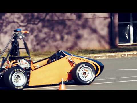
After another win on the national competition in 2018, UNICAMP E-racing got together to define the next steps, and that way the Artificial Intelligence division was created. Founded by four members, they had the objective of creating the first Driverless Formula SAE car of the Americas. A few months later and with a total of 12 members, the division had a complete roadmap to make this a reality.
This project, now open, is a polished version of the code that let to the first functional prototype. Here is the code and documentation of the lessons learning from that first year of development.
Although there are many sofisticated mapping and control methods that have amazing results, it was decided to take the simplest approach possible. That way the team could figure which areas required more attention and allowed us to get a working prototype as fast as possible.
The philosophies followed on the development:

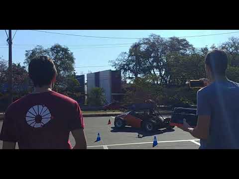
Develop an autonomous Formula SAE, capable of going through a track delimited by cones on both sides, in a safe, but high-performance way.


The software follows a very simple logic, that is based on the following pipeline:

Image processing and cone detection;
Find the middle of the track and steering target;
Communication with the car;
The car interface is made through a CAN bus. There the car sends feedback like speed, and receives commands as target steering and target speed.
The interface with the CAN bus was made through an USB-CAN adaptor.

The used camera has a USB 3.0 interface, that is connected directly on the processing board (Jetson TX2);
One of the main functionalities is mode selection, being able to isolate some parts of the system and simulate them separetly, making it easier to optimize parameters and to find errors.
In that mode, all the vision pipeline is substituted using a track file, that way simulating the cone detection. This mode is good for testing control strategies.
It simulates the car's behavior using a simple cinematic model (bicycle model). The communication with the simulation is made through a Virtual CAN, that way the behavior of the rest of the software don't need to change.
This option enables the reading of CAN messages instead of only writing as in the default mode. This is helpful for debugging as the read values aren't used in the control algorithm.
All the constants used are in one file (contants.py) for simplicity. These constants change the behavior of the algorithms and the main ones are explained below:
SHOW_IMG = False  # Display a window with the camera image and detected cones
SHOW_VIEWER = True  # Display a visualizer with a topdown view of the cones and the car
RUN_FLAGS = ["CAN_READ", "CAR_SIMULATION", "VISION_SIMULATION"] # operation options
...
CAPTURE_MODE = "ZED_SDK"  # ZED_SDK or OPENCV - The mode to be used to capture images from the camera
FLIP_IMG = False  # Invert the camera image if the camera was mounted upside down
...
MESURMENT_MODE = "STEREO"  # STEREO or MONO - Cone position estimation method
...Responsible for capturing the image from the camera, detecting cones on the image and estimating their positions.
There are two capture modes, one using the ZED camera SDK and the other using the OpenCV library. The OpenCV method can be used to run on other cameras.
There's only one detection method, using the neural network YOLO.
There are two estimation methods. They are:
-
Mono
Using previous information about cone size, the heigh of the bounding box is used to estimate its distance. Is relatively precise for cones nearby.
-
Stereo
Using the stereo image from the camera, it calculates the cone's 3D position with respect to the camera.
Two different control logics were used and tested. Both estimate the middle of the track and then based on it calculate the steering angle to keep the car in the middle.
There are several constants that can drastically change the controller behavior. Those constants determine limits and parameters to be optimized depending on the car and the track.
Simple method, that basically find the average cone position for the closest cones and steer to it. It aditionally does collision checks.
This method find cone pairs (blue + yellow) and gets the track middle from those pairs.
The CAN Interface sends and receives messages in the car's CAN bus. It's main role is abstracting the coding and decoding of CAN messages.
This block should be custumized for the application, possibly to even completely changed by other forms of interface.
Emulates the car using a cinematic bicycle model, emulate the CAN messages and the steering actuator.

The simulation of actuator response time has helped the detection of a few problems in the software.
Emulates the vision pipeline using a file containing a track defined by [x,y] of all cones. It also include measurement error and dropout.

Shows car state and draw the topdown view of the car and the cones.

Is used with the Car Emulator and Vision Emulator.
The actuator response time has not been taken into account in this software, making it hard to increase max speed.
Other cone detection method may be implemented to improve the latency of the system.
Adding a mapping module, making it possible to make the decisions on a longer period.
Adding speed control to the Controller should help with lap times.