This project was designed to be used for the 4x4 in Schools competition. It uses a Raspberry Pi, a TSL2561 light sensor and either a LSM6DS3 IMU or an ADXL345 3 axis accelerometer. All components and code comply with the 4x4 in Schools regulations.
The following steps are to setup and run the code for the raspberry pi. The next section outlines the hardware used in the project.
Follow the inscrution in the link to set up your raspberry pi for a first boot-up. If you have already got your pi working, feel free to skip this step. https://www.raspberrypi.org/help/noobs-setup/
Use the following steps to set up the Raspberry Pi for SSH. SSH allows you to access the terminal of your raspberry pi from a different computer. https://learn.adafruit.com/adafruits-raspberry-pi-lesson-6-using-ssh/overview
Use the following steps to set up the Raspberry Pi for use of the GPIO pins, and enable I2C and SPI. These are used to activate the LEDs/Buzzer, and communicate with the light sensor and accelerometer chips. https://learn.adafruit.com/adafruits-raspberry-pi-lesson-4-gpio-setup/overview
For the code to work, you are required to use the Adafruit Python GPIO library. To install it on your raspberry pi, follow the instruction provided in the link. https://github.com/adafruit/Adafruit_Python_GPIO
Download the files name x4x4, TSL2561, and ADXL345 from this GitHub repository, and copy them to the 'home' folder of your raspberry Pi.
If you have not already assembled the hardware and plugged it in, do so now. Follow the insturction in the next section if you are unsure how to do this.
Open up the terminal and type navigate to the directory you placed the code in. Type, 'python x4x4.py'. If you are unsure how to use the terminal, follow the tutorial in this link. https://www.raspberrypi.org/documentation/usage/terminal/
If the program is working correctly, follow the instructions in the link to allow the program to run at startup. http://www.instructables.com/id/Raspberry-Pi-Launch-Python-script-on-startup/
Attach the raspberry pi and components to the car, power up, and get driving! (Note, it takes roughly a minute for the code to get running).
- 1x Raspberry Pi
- 2x White LED
- 2x 220 Ohm Resistor
- 1x Bucky v5 power converter
- 1x ADXL345
- 1x TSL2561
- 1x Buzzer
- Wire
- Solder
- Soldering Iron
- HDMI cable
- Ethernet cable
- 5v microUSB power adapter
- Keyboard
- Mouse
- Computer monitor
VERTER 5V USB Buck-Boost - 500mA from 3V-5V / 1000ma from 5V-12V

With this converter, you can use any power source that is between 3 and 12 volts. I used a 9 volt battery. Solder you power cables (my 9v battery connector cables) to the holes labled VIN on the left hand side of the board. Make sure you put your positive cable into the hole labels '+' and your ground cable into the hole labeled '-'.
Next, solder your 5v output cable (input for the pi) into the hole on the right side labeled '+'. Then, solder your ground output cable (ground into the pi) into the hole on the right labeled '-'.
ADXL345 - Triple-Axis Accelerometer (+-2g/4g/8g/16g) w/ I2C/SPI


Because both of these chips run off of 3.3v, and use I2C, we will be able to combine the cables from both of the chips.
Solder a red wire to the 'Vin' pin on both chips. Connect both of these cables together, and leave a contact patch for another wire to plug into the pi. Do the same for the pins labled 'GND', 'SDA', and 'SCL'.
To enable I2C on the ADXL345 chip, solder the 'CS' hole to the '3v3' hole.
Simply solder the wires on the buzzer to your connections on the raspberry pi.
Through-Hole Resistors - 220 ohm 5% 1/4W - Pack of 25 Diffused White 3mm LED
On two LED's, solder two 220 ohm resistors to the positive ends. Then, solder you wire connection to your two LED connections on the pi. Next, solder two wires to the negative ends of the LEDs. Then, solder these two wires together, and solder this connection to your LED ground pin. You will have three individual pin connections to the pi. Finally, wrap the connections in electrical tap.
Each of the GPIO pins will be referenced to in the BMC Format.
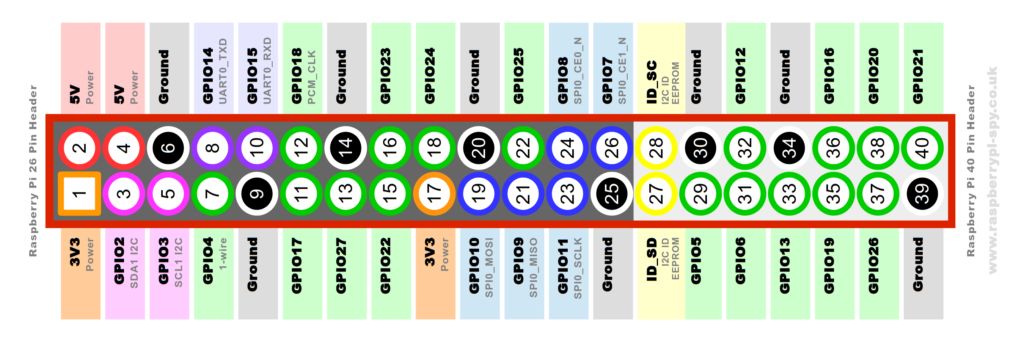
- Bucky Power Converter: positive (red) into 5v (pin 2), ground (black) into Ground (pin 6).
- Accleromter and Light Sensor: positive (red) into 3v3 (pin 1), ground (black) into Ground (pin 9), SDA (blue) into GPIO2 (pin 3), SCL (orange) into GPIO3 (pin 5).
- Buzzer: positive (grey) into GPIO21 (pin 40), ground (black) into Ground (pin 38).
- LEDs: positive1 (red) into GPIO20 (pin 38), positive2 (red) into GPIO16 (pin 36), ground (black) into Ground (pin 34).